Soldering an Inline DC Buck Converter/Voltage Regulator
The LM2596 DC voltage regulator/buck converter is able to take up to 40v and convert it down to as low as 1.5v. This is useful for many projects such as powering a Raspberry Pi or LED lights off a 3D printers power supply. This guide will cover how to wire one together. I will be using the eBoot buck converters in this guide but the premise should be the same no matter what buck converter you use.
[amazonDisclaimer]
Project materials:
| Item | Required? | Amount |
|---|---|---|
| LM2596 DC to DC Buck Converter | Yes | x1 |
| Wire/connectors (exact wire/connectors will vary from project to project) | ||
Tools needed:
| Item | Required? | Amount |
|---|---|---|
| Soldering Iron | Yes | x1 |
| Solder 60/40 | Yes | x1 |
| Wire Cutters/Strippers/Crimpers | Yes | x1 |
| Multimeter | Yes | x1 |
| Multimeter Alligator Clips | No | x1 |
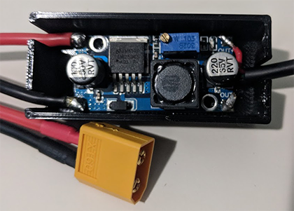
If you are using a connector system like JST or XT60, this would be a good time to check if your connections are polarized the right way. If you put the connection in a line, the same color wires should persist across the connection. If they are crossed, it is not good but usually easily fixable. Here is a picture of what to look for:

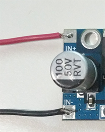
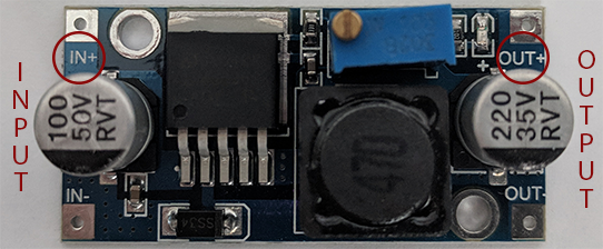
There are many ways that you can solder this on. I personally like to ‘tin’ the wires and the pad (put solder on the pad) and then heat the wire and place it on the pad until the pad melts and then take the soldering iron off and keep hold of the wire until it is solidly in place. This is why I like to use silicone coated wire because it doesn’t melt when doing this process. Do the same for both wires on the input side of the buck converter making ABSOLUTELY SURE that you have the wires in the correct place: Black wire on negative or ground and the red wire on positive.
Now double and triple check the wires are in the correct place. This includes through the connectors and to the power supply. A good way to do this is to use a multimeter with continuity checker.
When you have the input connections made, you can now dial the buck to the correct voltage. YOU NEED TO DO THIS BEFORE ATTACHING WHAT YOU ARE POWERING SO THAT YOU DON’T DAMAGE IT. It is easier to do this before soldering on to the output wires because we can use either allagator clips or push the pins of the multimeter in the small holes to help keep them in place when adjusting the voltage.
First, find the method used to regulate the power. On the ones I have linked, it is a gold screw in the corner of the blue rectangular object. Make sure that the buck converter is not touching anything that is conductive. I use a piece of cardboard and put the buck on that. Now, plug the buck in to the power source you are going to be using. Just make sure that you have access to the output pads of the buck. Then, plug in your power source and turn it on. Take your multimeter and place the pins on the output pads (black on ground/negative, red on positive). If you have allagator clips for your multimeter, it would make things a lot easier to use those instead of the pins and free up a hand. Turn the screw a little bit to see if the voltage is going up or down. If you are using the eBoot buck converters, counter-clockwise reduces the voltage and clockwise increases voltage. Once you find which way you need to go, continue to turn the screw until you get to the desired voltage. Once you have the buck dialed in, we can continue on.