Adding LED Lights to my Ender 3
LED lights are a cheap, easy way to light up your 3D printer. This is a guide of how I added LEDs to the top and under the Bullseye on my Ender 3. The jist of the guide would work for just about any 3D printer though.
First, the obligatory warning:
Please read the entire guide thoroughly and completely before ordering parts for this project. I am not to be held responsible for any harm done to the machine or yourself. You need to feel completely confident in what you are doing to use this route. If you have the slightest doubt about doing it on your own, please do not attempt this. I will be making kits for sale soon. This also may void your warranty on your machine.
I will present 3 options to connect the lights to the power supply:
- Open the power supply and create a new connection with JST connectors. (This is what I did.)
- Open the power supply and create a new connection with XT60 connectors. This is the same type of connector that is already in the Ender 3.
- Buy an XT60 splitter and use the already provided power connection assuming that you have an Ender 3. This one would save you from opening your power supply.
The parts for each of these options are listed in the table below. Click on the option you opt to use to reveal the parts needed.
Materials and Tools
Materials
| Item | Required? | Amount |
|---|---|---|
| LM2596 DC to DC Buck Converter | Yes | x1 unit |
| 6k LED Lights | Yes | x1 roll |
| 20AWG Wire | Yes | ~10ft |
| Round Automotive Power Switch | No | x1 switch | 1. New connection with JST Connectors |
| Silicone JST Connectors | x1 set | |
| 18-22AWG Red Fork/Spade Wire Connector | x2 | 2. New connection with XT60 Connectors |
| XT60 Connectors | x1 set | |
| 10-12AWG Yellow Fork/Spade Wire Connector | x2 | 3. XT60 Splitter |
| XT60 Splitter | x1 |
Tools
| Item | Required? | Amount |
|---|---|---|
| Soldering Iron | Yes | x1 |
| Solder 60/40 | Yes | x1 |
| Wire Cutters/Strippers/Crimpers | Yes | x1 |
| Multimeter | Yes | x1 |
| Metal Stepper Bit | No | x1 |
| Helping Hands | No | x1 |
Printed Parts
Other
If you are going to source your own materials, these are my suggestions:
- 24AWG wiring is the thinnest wiring you should use (the higher the number, the thinner the wire). Anything below that would not handle power well and could have bad consequences. I recommend 20 AWG because it is easy to come by. Also, I would recommend getting silicone coated wire over PVC coated because it does not melt as easily. It costs a bit more, but if you are going to be using the wire for more projects than just this one, you will thank me.
- The Bullseye LED clip that I designed for 8mm wide LED strips, wider strips will not work. If there is enough demand, I will make clips in various sizes.
- When choosing LEDs, you will see numbers anywhere from 3k-6.5k This number is the color temperature of the light. The lower end of the spectrum is more of a yellow light while the higher end displays as more of a blue light. I chose 6k because it is on the top end of ‘natural daylight’.
- There are also indoor and outdoor LEDs. If you are only going to use them to light up your 3D printer, indoor will work just fine.
- You also need to pay attention to the voltage the LEDs run on. In the link I have supplied, the LEDs run on 12 volts. If I plugged them in to the Ender 3 power supply, they would fry instantly. The buck converter is what is used to take the 24 volts from the power supply and step it down to the 12 that is needed to power the LEDs safely.
Guide
Printing parts:
While I do the rest of the process, I like to get my parts printing. I used my LED Bar to attach the lights to the top of my Ender and my Bullseye LED clip to illuminate the front of the print if you have the newer version of the Petsfang Bullseye by dpetsel. There are also different versions that do the same job from Sixteenbit and Rotiik.
Getting everything ready
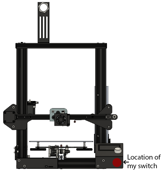
The next thing to do is to get everything ready. Also, if you are going to add a switch to the printer, I would decide on where you are going to put it. I drilled a hole in the front of the screen bracket and put my switch there. If you are using the switches I linked, you would go to the 7/8 step.
Then, the next thing I did was to get a rough estimation on wire length and where I am going to run them. For the top of the Ender, I ran the wire from where the power switch is going to be, up through the T slot in between the power supply and frame, and finally left a little extra on either end just in case. For the one under the Bullseye, I ran the wire from the power switch, along the front side of the bottom of the frame (where the ribbon cable for the screen is), in to the control box, up through the mesh that contains the other wires going to the extruder, and left about 5 inches more than I thought I needed just in case. You can do a loose fit now but try to keep it as accurate as possible while going along the mesh.
After that, I got the LEDs cut to size. If using the LEDs I linked, you need thirteen (13) sections of LEDs. In this case, every 3 LEDs is considered a section. You would cut along the line where it says to cut. There are 2 oval copper pads, you cut across them as well. The light below the Bullseye only requires 1 section.
Adding a connection to the power supply
The first thing you need to do is add a connection to the power supply to power our LEDs. There are multiple ways that you can do this.
- You can use a XT60 splitter and cut one end off to solder to the buck converter. This is the easier of the options because it does not require you to open the power supply and use a connection that is already supplied by default with the Ender 3.
- You can open the power supply and make a new connection. You can do this with either a XT60 connector or JST connector use the corresponding fork/spade wire connectors to make a connection to the power supply.
Option 1:
If you are using an XT60 Splitter, just cut off one of the female ends. Once you do that, you can skip this next part and move on to the next step
Option 2:
First, we need to drain all the power from the machine. While your printer is on, unplug it from the wall. Don’t just turn the power switch off, you need to actually disconnect it from the wall. This will allow the capacitors to draw all the power that is stored in them and making the power supply safer to open.
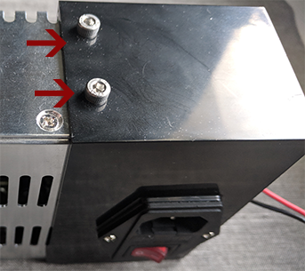
On the Ender 3, there are only two (2) screws that you need to take out to access the parts that we need to make the connection needed to power our buck converter.
Once the cover is off, you should see something like this:
Our next task is to use our fork wire connectors and attach them to the ends of our male connector to that we can attach it to the power bar. To do this, we need to strip the end of the wires just enough to insert them in to the metal parts of the fork wire connector shown in the picture below:
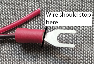
Once we have the wires stripped to the correct length, we use our crimpers to crimp the fork wire connector on to the wire. Slide the wire in to the wire connector until the wire is to the end of the metal as shown in the last picture. Now, use your wire crimpers to mash the metal to the wire. Usually, the crimpers will have a colored dot next to the actual crimping mechanism that would correspond with the color of the wire connector. That is the one you should use. When you are done crimping, give the wire and the wire connector a light tug against each other. The connection should be tight and not move. Same steps for the other wire.
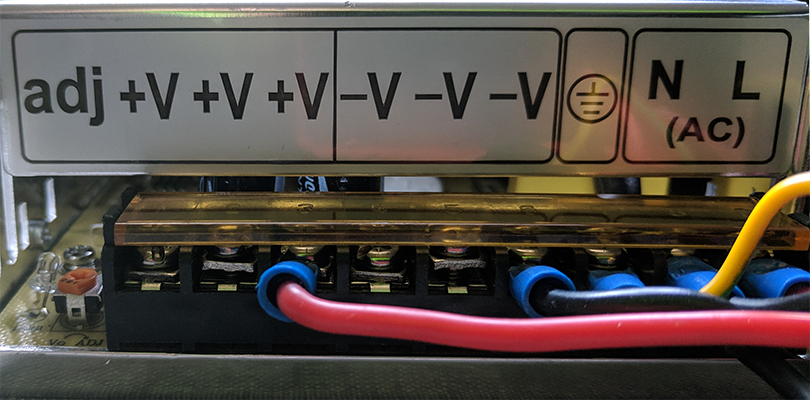
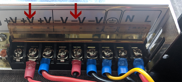
Now that we have the male end of our connector ready, we can put it in to our power supply. Please make EXTRA sure that you are placing the wires in the correct place. We DO NOT want to mix up our positive and ground wires. If you are using an Ender 3, Connect the wires as shown below:
Once you have the wires screwed in snugly, you can close up the power supply. I would recommend making sure that all the wires are snugly in place. When I opened up mine, one of the ground was so loose that it popped off of where it was supposed to be. I simply use a pair of pliers to gently make the connection tighter so that it would stay on by a friction fit. Carefully finagle the wires so that you have the connection out of the housing of the power supply and replace all screws.
Soldering the buck
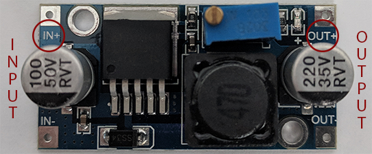
Now that you have power coming from the power supply, you need to attach the female end of the wire you used to the buck converter. Buck converters are polarized so there is a specific way you need to solder your wires on to them. The EBOOT bucks I use have markings next to the pads and an arrow on the bottom of the board to show which direction power is flowing. Both examples are shown in the picture below.
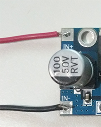
Now that you know which way power is flowing, we can solder on our wires. First strip your wires just long enough to be the length of the pad. Generally, you do not want extra of the core of the wire exposed. This could cause arcing if coming close to another metal object and become a hot mess and a very bad day. If you are using my 3D printed buck case, the input wires stick straight out like shown below.
There are many ways that you can solder this on. I personally like to ‘tin’ the pad (put solder on the pad) and then heat the wire and place it on the pad until the pad melts and then take the soldering iron off and keep hold of the wire until it is solidly in place. This is why I like to use silicone coated wire because it doesn’t melt when doing this process. Do the same for both wires on the input side of the buck converter making ABSOLUTELY SURE that you have the wires in the correct place: Black wire on negative or ground and the red wire on positive.
Now double and triple check the wires are in the correct place. This includes through the connectors and to the power supply. A good way to do this is to use a multimeter with continuity checker.
When you have all those connections made, you can now dial the buck to the correct voltage. YOU NEED TO DO THIS BEFORE HOOKING THE LEDs UP SO YOU DON’T BLOW THEM.
A good thing to do is to make sure that the wires of the connectors are polarized the correct way. Sometimes, one of them will be backwards. If that is the case, you should be able to take a pin to the male end and push the tab down on either side and slide the wires out. Then you can just slide them back in the correct place. They will be correct most of the time, but not all.

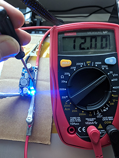
First, you should see a screw somewhere on the buck converter. On the ones I have linked, it is a gold screw in the corner of the blue rectangular object. Now, plug the buck in to the printer by using the connection method you used. In my case, I plugged the JST connection between the buck and the power supply. Make sure that the buck converter is not touching anything that is conductive. I use a piece of cardboard and put the buck on that. Just make sure that you have access to the output pads of the buck. Then, plug in your printer and turn it on. Take your multimeter and place the pins/alligator clips on the correct pads (black on ground/negative, red on positive). If you are using the eBoot bucks turn the screw counter-clockwise until you are down to 12 volts. If you are using a different buck, turn the screw a little bit to see if the voltage is going up or down. Once you find which way you need to go, continue to turn the screw until you get to 12 volts. Once you have the buck dialed in, we can continue on.

Connecting the Wires to the Switch

Now, this is where you get to make a decision: Solder the wires directly to the pins of the switch, or use an electricians setup. Basically this setup combines all the wires in to a wire nut and adds a tail that would get soldered on the prongs of the switch. You could go really fancy and even get some sliding spade connectors to attach to the pins of the switch but I have had a hard time finding ones that fit.
Every switch can be different so be sure that you are aware of what prong belongs to what. I will be assuming that you are using the switches that I linked. There will be one prong a different color than the rest and typically copper. This is your ground prong. All of your black ground (black) wires will be attached to this prong. The middle prong is your power input (coming from the buck). The outer silver prong is your load. This will be the prong you attach the LED strips to.
If you are soldering the wires directly to the pins, the easiest method would to strip the wires long enough that you are able to twist them together a couple of times, solder/tin the wires to fuse them together, and then solder them to the pin. I would also recommend putting heatshrink over the pin just for the added protection. I find that a good pair of helping hands makes things a lot easier to manage. I cover the alligator clips with a piece of sleeve from an old ethernet cable to help protect the things I am working on.
Wiring and Placing the LEDs
Next, attach the LED strip that goes on the top of your printer. This should be pretty self explanatory. Strip the wire so that it is the length of the pad and tin the end. Tin the pad so the wire has something to attach to. Attach the black ground wire to the ground or negative pad and attach the red wire to the positive pad.
Now, before we attach the other LED strip, we are going to make sure everything works. Plug the setup in to your printer, turn the printer on, make sure that the hanging wire without the LEDs on it is not touching anything conductive, say “Let there be LIGHT!”, and flip the power switch for the LEDs (if you have one). If everything has gone well so far, you should have more light in the room. Just don’t stare in to the LEDs as they can damage your eyes.
Next, feed the wires, LEDs, and buck (if the buck doesn’t fit, you’ll have to unsolder one end, feed the wires through, and solder the connections again) through the hole that you created for the switch. Once you do that, you can place the top LEDs in to the top bar and clip them in to place. I used some hot glue over the seams of the clips to help hold them in place. I also made a big glob on the end of the LEDs where the wires are connected to provide some strain relief for the wires. When that is done, route your wire where you would like it to go. I placed mine in one of the ridges of the 2020 extrusion behind the power supply. I didn’t take the power supply completely off but I did loosen it enough that I could move the wire between the power supply and the 2020 extrusion and then tightened the power supply back up to the frame.
Now for the hard part (at least for the Ender 3). I ran the other wire (still without the LED on) next to the ribbon cable for the screen, in to the control box, out through the mesh going to the extruder (tips below), and finally through the bullseye to my clip. I found the easiest way to get the wire to the extruder is to push the wire as far in to the mesh as you can. I actually got to about half way before meeting significant resistance. Then, I pushed the mesh down from the top until I was able to pull the rest of the wire through. After replacing the mesh and the zip tie that was on the top, I cut the wire to length while leaving like an extra inch, stripped the ends, and soldered the LEDs to the wire. This is easiest done with multiple people or with helping hands. I then used the adhesive that came with the strip, pushed it in to place of the Bullseye clip, and then hot glued the ends to help keep it in place and provide wire relief.
Now clip the LED clip in to the Bullseye, push the switch in to the hole if you haven’t already, turn the power supply on, flip the switch for your lights, and have yourself some warm cookies with milk.
Conclusion
This setup is very nice for lighting up your print. It is good for people like me who has my printer in another room and prints during the night frequently. It can be improved upon though, like adding arms that could angle your lights from the front and back to help eliminate the shadow from the x-axis arm. Making a system like this is on my todo list.
amazon Amazon Associates Program
As an Amazon Associate, I earn from qualifying purchases. There is no extra cost to you.
Thanks for the ideas, as I was thinking of installing leds on my CR-20. Just a question, why don’t you use 24V leds directly connected to the power supply instead of a DC-DC 24 to 12V converter to feed 12V leds ?
It’s what I had in my house already from other projects.
Thanks, LTM for the detailed instructions. Will make one from the PSU and buck converter per instructions.
Images are not loading for this article. Reference is to http://localhost/wp-content/uploads/ and of course wont work on the web.
Thanks for letting me know. I will try to get them fixed this weekend.
Any update on those pictures? I am really interested in giving this a go, sounds like a great solution.
Yeah just got them fixed… I guess when I transferred to a new hosting (again), the urls got messed up.
Hi, thanks for the write-up. I find that I just don’t get the layout of the led strips and what the finished project should look like. The wiring is very simple, and I think I understand how the strips feed into the slots. I don’t get how the corners of the light strip are laid out, nor the running of the wires relative to the frame. Pictures would be much appreciated.